Modal Sensitivity calculates and orders multiple SDM solutions over a user-defined solution space of physical properties.
This command shows you how much physical modification is necessary to change the modal properties of a structure so that they match Target values.
This command uses SDM to solve for new mode shapes over a solution space of FEA Properties.
The solution space is defined by the Minimum, Maximum and Number of Steps of each FEA property.
Solutions are ordered from best to worst.
The best solution is the one that minimizes the percent difference between Target and Solution modal parameters
Calculation over the entire solution space guarantees that the best solution will always be found
The following Table lists the FEA properties that can be used to define a solution space for this command.
|
FEA Object |
Property |
Target Modal Parameter |
|
Spring |
stiffness |
frequency |
|
Damper |
damping |
damping |
|
Mass |
mass |
frequency, damping |
|
Rod |
cross sectional area, |
frequency, damping |
|
Bar |
cross sectional area & inertias, (Elasticity, Poisson's ratio, Density) |
frequency, damping |
|
Plate |
thickness, |
frequency, damping |
|
Solid |
(Elasticity, Poisson's ratio, Density) |
frequency, damping |
FEA Properties and Target Modal Parameters.
Material properties are Young's Modulus of Elasticity, Poisson's ratio, and Density
When this command is executed, the Shape Table selection dialog box will open.
Choose a Shape Table file containing the UMM mode shapes of the unmodified structure, and click on OK.
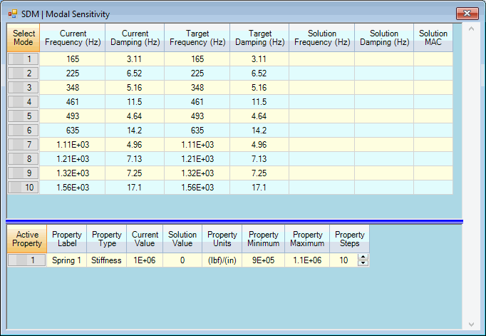
The Modal Sensitivity window will open next, displaying two spreadsheets
The UMM mode shapes must animate correctly on the structure model before using them with this command.

Modal Sensitivity Spreadsheets (in Upper/Lower Display format).
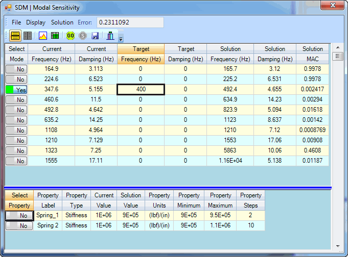
The upper spreadsheet lists the current, target & solution modal parameters.
Current Frequency & Damping are the modal parameters for the unmodified structure.
Target Frequency & Damping are the User-defined target values
Solution Frequency & Damping are the results of the SDM calculations .
If one or more mode pairs are selected, then only those solution parameters are compared with target modal parameters.
If no target modal parameters are entered, the SDM solutions are listed in the order calculated.
The lower spreadsheet lists the current and solution values of the Properties of all visible FEA Objects on the structure model.
Each Property on the lower spreadsheet has a Minimum, Maximum and Steps column. These three columns together define the solution space for each Property.
The Minimum, Maximum, and Steps of all or selected Properties define the solution space. SDM solutions are calculated for all values in the solution space.
The user-entered Minimum and Maximum Property values define the lower and upper bounds of the FEA Property in the solution space
The user-entered Property Steps is the number of steps to be evaluated between the Minimum & Maximum Property values
The total number of SDM solutions is the product of the Property Steps of all or selected FEA Properties
If Minimum = 1, Maximum = 10 and Steps = 10, then 10 SDM solutions would be calculated using Property values (1,2,3,4,5,6,7,8,9,10)
If three FEA Properties each have 10 Steps, then the total number of SDM solutions is 1000
If mode pairs are selected in the upper spreadsheet, an Error function is calculated, and used to order the solutions from best to worst.
The error is a summation of terms, one for each non-zero Target & Solution frequency and/or damping pair in the upper spreadsheet.

where:
Fs = solution frequency, Ft = target frequency
Ds = solution damping, Dt = target damping
Each frequency term is the absolute difference between the Solution & Target frequency divided by the Target frequency
Each damping term is the absolute difference between the Solution & Target damping divided by the Target damping
The minimum error for all calculated solutions is listed in the Error box on the Toolbar
Depress the Select Mode buttons to select each mode pair to be used in evaluating the Error function.
Only the modal parameters of the selected mode pairs will be used to calculate the Error function.
Enter a Target frequency and/or damping value into the upper spreadsheet for each selected mode pair to be used for calculating the Error function.
If no Target modal parameters are entered for a selected mode pair, that pair will be excluded from the Error function calculation
Depress the Select Property button in the lower spreadsheet to select each property to be used in the calculations
Enter Property Minimum, Maximum and Steps into the lower spreadsheet to define the solution space for each FEA Property
If no properties are selected, the Minimum, Maximum & Step of all FEA Properties in the lower spreadsheet will be used to define the solution space.

Best Solution Shown in the Spreadsheets.
Calculates all SDM solutions for all or selected FEA Properties in the user-defined solution space in the lower spreadsheet
Stops the SDM calculation process and displays the solutions that have already been calculated
When the SDM calculation is completed or stopped, a Solution Scroll Bar will be enabled on the right side of the Modal Sensitivity window.
Solution values are displayed in both the upper & lower spreadsheets by scrolling the Solution Scroll Bar
If mode pairs are selected in the upper spreadsheet, the solutions are ordered from best to worst according to their Error function values
The best solution is displayed when the scroll is at the top of the Solution Scroll Bar
The worst solution is displayed when the scroll is at the bottom of the Solution Scroll Bar
If no mode pairs are selected in the upper spreadsheet, the solutions are displayed in the order in which they were calculated
Toggles the spreadsheet display between Upper/Lower and Left/Right format.
When this command is checked, the Modal Sensitivity solutions are displayed using two spreadsheets.
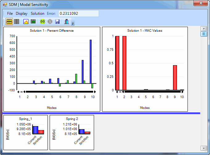
When this command is checked, the Modal Sensitivity solutions are displayed graphically, as shown below.
The upper left bar graph shows the percent difference between the Target and Solution frequency & damping of each mode
Hover the mouse pointer over each bar on a bar graph to display its values
The upper right bar graph displays the MAC values between the Solution & Target mode shapes
The lower bar graph displays the Current and Solution values of all or selected Properties

Bar Chart Display
Saves the mode shapes into a Shape Table that result from the current FEA Properties in the lower spreadsheet.
Before executing this command scroll the Solution Scroll Bar on the right hand side to display the desired solution.