The commands in this menu are used to mesh (subdivide) all (or selected) Objects on a structure model.
All original Objects are replaced by new Objects of the same type.
The following types of Objects can be meshed,
Line Objects: Lines (and FEA Springs, Dampers, Rods, and Bars).
Triangle Objects: Surface Triangles (and FEA Plates).
Quad Objects: Quad Surfaces (and FEA Quad Plates).
SubStructures: All Line, Triangle, and Quad Objects referenced by a SubStructure .
EDGE: The term "edge" refers to either a Line Object or the edge of a Triangle or Quad Object.
Subdivides the edges of all selected Objects using a number of evenly spaced midpoints.
Meshing a Line Object divides it into equal segments.
Meshing a Triangle or Quad Object evenly subdivides each of its edges.
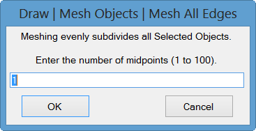
When this command is executed, the following dialog box will open. The number of midpoints is the number of Points that will be added between the endpoints of each Line Object or Surface Object edge.
Enter the number of midpoints, and click on OK.

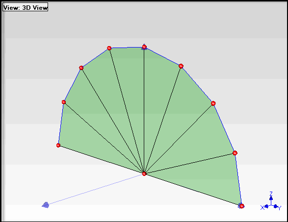
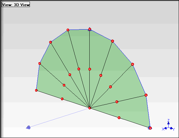
Meshes the longest edges of all selected Objects. This command ensures that only the "long edges" of an Object will be meshed.
Edges are meshed so that no edge is longer than half of the longest edge found among all of the selected Objects.

Before Meshing Longest Edges.

After Meshing Longest Edges.
To ensure that all Line & Surface Objects are properly meshed, it is better to create a new SubStructure with all of the Line & Surface Objects in it, and then mesh the SubStructure.
Select all of the Points being referenced by the Objects to be meshed.
Execute Draw | SubStructure | Add Objects to SubStructure.
Click on New SubStructure in the dialog box that opens, and enter a name for the new SubStructure into the box that opens.
Select the new SubStructure and mesh it.
If all of the Points referenced by the Objects to be meshed already have Animation equations, then new Animation equations will be automatically created for all of the new mesh Points when one of the Mesh commands is executed. This allows you to start with a simple (stick or surface) model with only a few Measurement Points on it, and create a meshed model with many more Points, including their Animation equations, To use this feature,
Create Animation equations for the Measurement Points.
Mesh the model to add more Points with Animation equations.
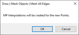
If Animation equations were already created for the Points on the Objects to be meshed, then during meshing the following dialog will open informing you that Animation equations will be created for all of the new Points.

Photo realistic or solid models (with many Points) are better for showing shape data in animation to others. A short-cut method for animating shapes on more complex photo realistic or solid models (with many Points) is to first animate them using a simple stick model, and then use ME'scope Interpolation to animate the complex model. The following steps outline this process,
Construct a simple stick model using only enough Points for the Measurement Points on the test article.
Animate the shape data (ODS's, mode shapes, etc.) on the stick model.
Mesh the stick model to create more nearest neighbor Points for Interpolation to the complex model.
Convert all of the Interpolated equations on the meshed stick model to Measured equations.
Use the Draw | Edit and Draw | Drawing Assistant commands to superimpose the complex model on the stick model in the same Structure window.
Create Interpolation equations on the complex model from the Measured equations of the nearest neighbors on the stick model.