When Draw | Drawing Assistant is executed, the Drawing Assistant tabs are displayed above the Substructures spreadsheet in the Structure window, as shown below. With the Drawing Assistant, there are several ways to create a 3D mode of the test article;
Choose a Substructure from the Substructure Library
Create a new Substructure starting with a editable Substructure (a line, plate, cube, circle, cylinder, etc.)
Extrude or Revolve a 2D Substructure to create a 3D Substructure
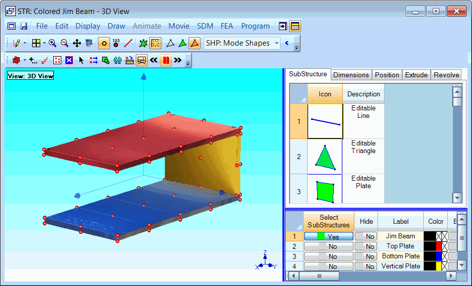
Structure Window Showing Drawing Assistant Tabs.
This tab contains a browser of the Substructures in the Substructure Library.
Double click on a Substructure in the Library browser to add it to the current model in the Structure window.
Execute File | Save in Library to add any structure model to the Substructure Library.
The Substructures with green surfaces at the top of the Library browser are called editable Substructures.
The dimensions and number of points in each direction can be changed on an editable Substructure.
Depending on its coordinate type, the dimensions of an editable Substructure are;
Rectangular: Width, Height, Length.
Cylindrical: Radius, Tangential Angle, Length.
Spherical: Radius, Tangential Angle, Elevation Angle.
The Length, Width, and Height dimensions of the selected Substructure can be changed on this tab.
The selected Substructure can be rotated about its Local or Global (X, Y, Z) axes using the controls on this tab.
The Local origin of the selected Substructure can also be translated with respect to the Global axes.
The selected 2D Substructure can be extruded into a 3D Substructure using the controls on this tab.
The selected 2D Substructure can be revolved into a 3D Substructure using the controls on this tab.