There are two requirements for matching the DOF of each measurement (M#) to a Point & direction of the structure model.
The Point number of each test Point on the model must match the Point number in the Roving DOF of the measurement (M#) taken at that Point.
The Measurement Axes of the Point with the matching Point number must coincide with the actual direction of measurement that the measurement (M#) was taken in at that Point.
To initiate Point numbering on a model,
Execute Draw | Points | Number Points in the Structure window with the model in it.
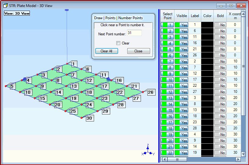
A floating Number Points dialog box will open, as shown below. You will control the Point numbering process from this dialog box.
Start with the Point at the origin of the Global axes, and click near each Point on the model to number it, as shown below.
If you click on the wrong Point, enter the correct Next Point Number into the Number Points dialog, and begin Point numbering again by clicking near the next Point to be numbered
When you have numbered all 30 Points, as shown below, click on Done in the Number Points dialog box

Plate With 30 Points Numbered.
NOTE: Point numbering places the Point number in the Point Label of each numbered Point.
Drag the blue splitter bar to the left to display the Label column in the Points spreadsheet.
Point numbers are displayed on the model by executing Display | Display Objects | Points | Point Labels ![]() .
.
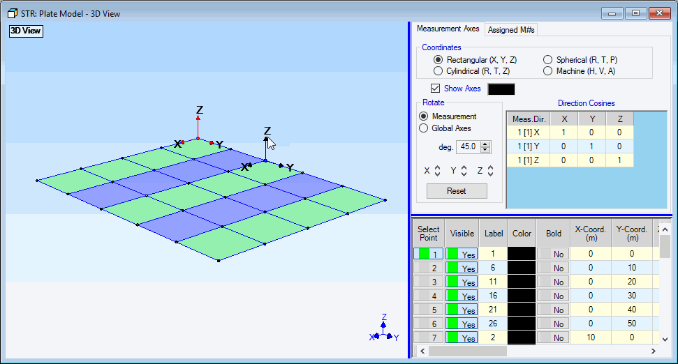
Each Point on a structure model has its own Measurement Axes. The Measurement Axes specify the directions in which measurements were made at each Point.
NOTE: Measurement Axes directions are defaulted to coincide with the directions of the Global Axes, which are displayed in the lower right corner of each View in the Structure window.
Execute Draw | Assigned M#s | Measurement Axes ![]() .in the Plate Model window to display the Measurement Axes at each selected Point
.in the Plate Model window to display the Measurement Axes at each selected Point
The Measurement Axes and Assigned M#s tabs are now displayed above the Points spreadsheet.
Notice that the Edit | Select Objects | Click Select ![]() command is also enabled
command is also enabled
Hover the mouse Pointer near a Point to display its Measurement Axes
Execute Edit | Select Objects | Select All ![]() to display the Measurement Axes of all of the Points
to display the Measurement Axes of all of the Points
Execute Edit | Select Objects | Select None ![]() to hide the Measurement Axes on the model
to hide the Measurement Axes on the model

Plate Structure Showing Measurement Axes.
Notice that the axis Coordinates are Rectangular on the Measurement Axes tab, and that the axis directions coincide with the Global (X, Y, Z) axes in the lower right corner. In this case the Measurement Axes at each Point are oriented with the Z direction pointing in the vertical direction, which also coincides with the direction of measurement at each Point.