Creating an Acoustic Surface
NOTE: The commands in this tutorial are only available if the VES-3600 Advanced Signal Processing option is authorized by your ME'scope license. Check Help | About to verify authorization of this option.
An Acoustic Surface is a special type of SubStructure that is used to display acoustic data. Acoustic data is typically taken on a grid of spatial Points in the vicinity of one or more noise sources. SPL , Sound Power & Acoustic Intensity data is typically displayed on an Acoustic Surface. Acoustic surfaces are easily created by using the Drawing Assistant in the Structure window.
-
Each measurement Point on an acoustic surface is surrounded by an area that is automatically calculated when the surface is generated.
-
A normal vector (at right angles) to the surface is also calculated for each measurement Point.
-
The surrounding area and normal of a Point are used to calculate Sound Power through the surface from Intensity data.
Rectangular Surface
-
Execute Project | New Project to start a new Project.
-
Execute File | New | Structure to create a new Structure window.
-
Execute File | Structure Options in the Structure window.
-
On the Units tab in the File | Structure Options box, choose Meters from the Length Units list, and click on OK.
-
Execute Draw | Drawing Assistant  in the Structure window.
-
On the SubStructure tab, double click on the Editable Acoustic Surface.
-
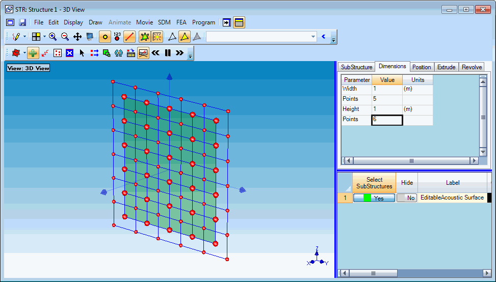
On the Dimensions tab, enter the following changes.
Width: 1 m
Points: 5
Height: 1 m
Points: 6

5 by 6 Meter Acoustic Surface.

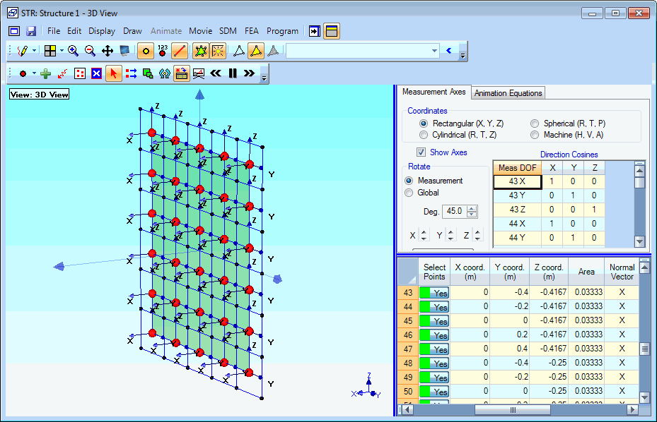
Acoustic Surface Showing Areas & Normals.
Each of the 30 bold measurement Points is surrounded by 4 Points which define its acoustic area. Acoustic areas & normals are calculated when an acoustic surface is created in the Drawing Assistant. Acoustic areas & normals are listed in the Points spreadsheet, and must be edited if the Point coordinates are changed.
![]() in the Structure window.
in the Structure window.
