This menu is also displayed when you right-click in the graphics area in a Structure window
Centers the Structure window in the Work Area of the ME'scope window.
Repeated execution of this command alternately centers the window and returns it to its former position.
Moves the vertical blue splitter bar horizontally to show or hide the Objects spreadsheet.
The properties of all Objects of the current Object Type are listed in the Objects spreadsheet.
Execute Edit | Current Type to select the current Object Type from the list of Objects.
Shows or hides the Structure window Toolbars. If checked, the Structure window Toolbars are shown.

If checked, displays all Points as dots on the structure model.
Points are automatically displayed and all of their properties are listed in the Objects spreadsheet when Points is chosen in the Edit | Current Type list. Point size can be changed on the Display tab in the File | Structure Options box.

If checked, displays the Point Label next to each Point on the structure model. Point labels use the following format;
Point label format = row number in the Points spreadsheet [ text from the Label column in the Points spreadsheet ]
Point text Labels are optional. Labels are used to create Measured animation equations by matching M# DOFs to Points & directions on a structure model.
If checked, displays the acoustic normal vector at each Point.
If checked, displays the Point Icon for each Point, if it has an Icon.
Points Icons are optional. Point Icons are defined in the Icon column of the Points spreadsheet.
If checked, displays the Lines on the structure model.
Lines are automatically displayed and all of their properties are listed in the Objects spreadsheet when Lines is checked in the Edit | Current Type list.
If checked, displays Line text Labels on the structure model.
Line text Labels are optional. Line text Labels are entered into the Label column in the Line Objects spreadsheet.
Surfaces are automatically displayed and all of their properties are listed in the Objects spreadsheet when Surface Triangles or Surface Quads is checked in the Edit | Current Type list
Surface colors are changed in the Color column of the Surface Triangles or Surface Quads spreadsheets.
If a Surface is also referenced by a SubStructure , its color can also be changed in the Colors column of the SubStructure spreadsheet.
If checked, Surfaces are not displayed on the model.
If checked, Surfaces are displayed and filled with their Surface color.
If checked, Surfaces are displayed in outlined format using their Surface color.
If checked, Surfaces are displayed using their Surface textures, if available.
If checked, Surfaces are displayed as transparent Surfaces.
If checked, Surface text Labels are displayed on the structure model.
Surface text Labels are optional. Surface text Labels are entered into the Label column on the Surface Objects spreadsheet.
If checked, lighted Surfaces are displayed on the structure model.
See Lights Tab in the File | Structure Options section for details on surface lighting.
If checked, Surface normals are displayed on the structure model.
Surface normals are used to display surfaces with lights and hidden lines.
If executed, the Surface normals of all (or selected) Surfaces are reversed in direction.
If checked, FEA Objects are displayed on the structure model.
FEA Objects are automatically displayed and all of their properties are listed in the Objects spreadsheet when an FEA Object is chosen in the Edit | Current Type list
If checked, FEA Objects text Labels are displayed on the structure model.
FEA Object text Labels are optional. FEA Object text Labels are entered into the Label column in an FEA Objects spreadsheet.
One of the four Views (X view, Y View, Z view, 3D View) is always the active View.
Click on a View to make it active.
Or execute its command in the Display | View menu
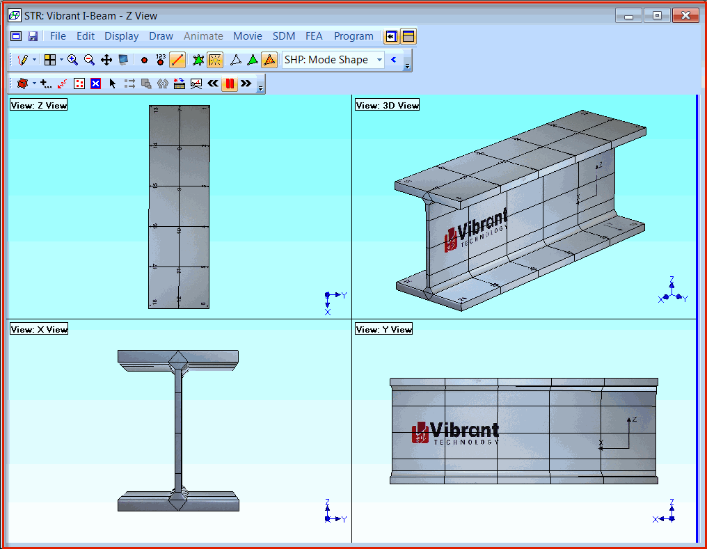
Either the Quad View or one of the four Views (X view, Y View, Z view, 3D View) is always displayed in the Structure window graphics area.
Double click on a single View to display the Quad View.
Double click on one of the Views in the Quad View to display it alone.
Displays the active View from the opposite side.

Structure Window in Quad View.
Initiates a display Zoom operation. After executing this command,
Move the mouse pointer into the View to be zoomed.
The mouse pointer will change to the cross when it enters a View.
Move the Zoom pointer to a corner of the area to be zoomed.
Click & drag to draw a Zoom Box on the area to be zoomed.
Move the Zoom pointer out of the graphics area to cancel a Zoom operation.
Click on a View to make it active.
Spin the mouse wheel to Zoom the display of the structure model in or out.
Restores a full display of the structure model in the active View.
Enables the Pan operation in the active View. Panning moves the structure model in a View.
Hold down the Shift key to enable a Pan operation.
Or execute Display | Pan ![]() to enable a Pan operation.
to enable a Pan operation.
Move the mouse pointer into a View.
The mouse pointer will change to a cross when it enters a View.
Click & drag to Pan the structure in the active View.
Move the cross pointer out of the graphics area to terminate the Pan operation.
Re-centers the structure model in all four Views in the Structure window.
The View Control is used to;
Rotate the structure model in the 3D View.
Zoom , Pan, or change the Perspective distance of the structure model in the active View.
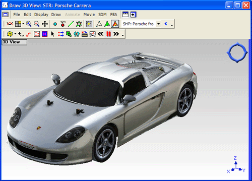
When this command is executed, the View Control is displayed in its sleep state in the upper right corner of the active View.
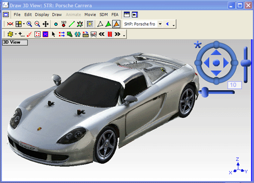
Move the mouse pointer to the upper right corner of the View to wake up the View Control, as shown below.

View Control in the Sleep State.

View Control in the Awake State.
Each part of the View Control performs a different function;
Click on an arrow to Rotate the structure model.
Click & drag the circle clockwise or counter-clockwise to Rotate the structure model.
Click & drag to Pan the structure model.
Click & drag to Zoom the structure model.
Click & Drag to change the Perspective distance from the structure model.
Click on the star to Reset all View Control parameters to default values.
These commands control the continuous rotation of the structure model only around the vertical axis in the 3D View.
Successive execution causes the model in the 3D View to rotate faster in a counter clockwise (CCW) direction, or slower in a clockwise (CW) direction.
Stops continuos rotation of the model in the 3D View.
Successive execution causes the model in the 3D View to rotate faster in a clockwise (CW) direction, or slower in a counter clockwise (CCW) direction, in the 3D View.