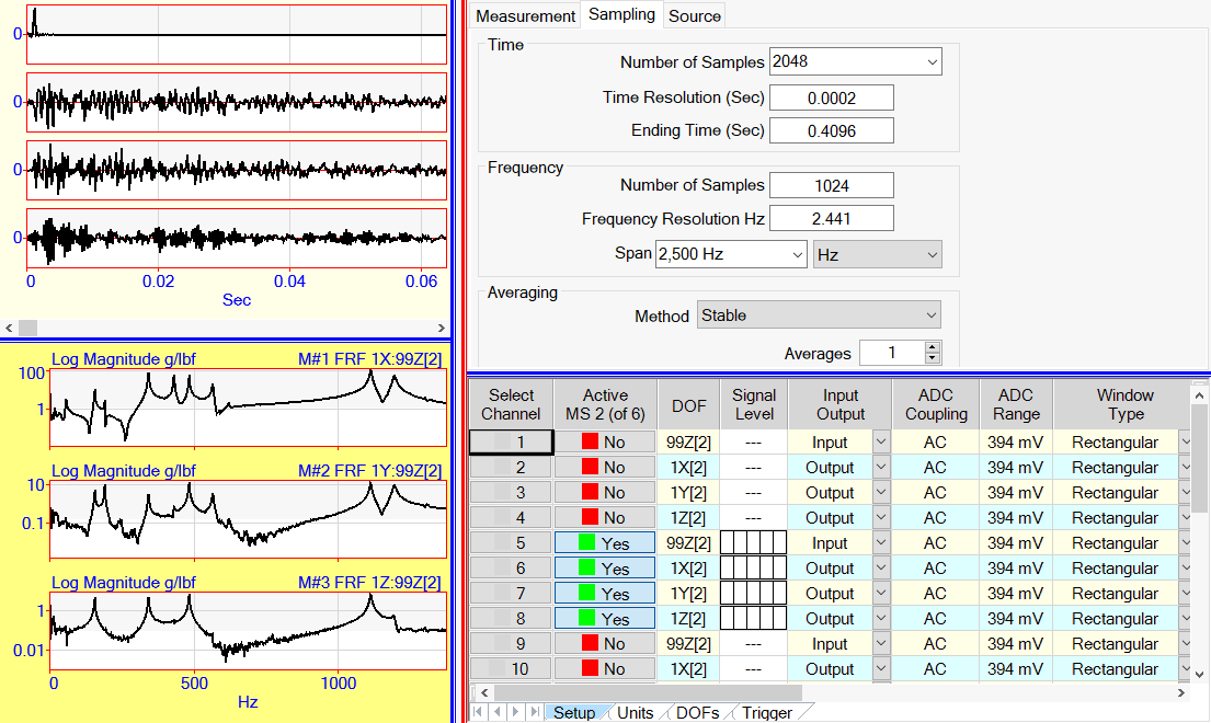
The Channels spreadsheet list the properties associated with the Front End acquisition channels
Each row in the Channels spreadsheet contains the properties of one channel.
Each column of the spreadsheet contains a property of all Front End channels.
Drag the Vertical Red Splitter Bar to the left to display more of the Channels spreadsheet.

Acquisition Window Showing the Channels Spreadsheet.
Three tabs (Setup, Units, and DOFs) are displayed below the Channels spreadsheet which define the properties of each front end channel.
The Select Channel, Active & DOF columns are common to all Channel spreadsheet tabs.
Used to make channels active or inactive. If a channel is active, data will acquired for that channel when data is acquired from the front end.
To make a channel active, click on its Active button until it reads Yes.
To make two or more channels active, select them in the Select Channel column and double click on the Active column heading.
When data is acquired from the front end, a time domain waveform is displayed in the upper graphics area for each active Channel.
Used to define the channel DOF. A DOF is typically the Point number & direction of the sensor location on the test article.
Using channel DOFs is optional, but it is strongly recommended as a convenient way of identifying where measurements were made on a test article.
For example, a DOF = 1X means the sensor is located at Point No. 1 on the structure and senses motion in the X direction.
Click on the channel property cell to toggle its button, edit its text contents, or select one of the choices from a drop down list.
Or double click on a property column heading to change the property of all (or selected) channels.
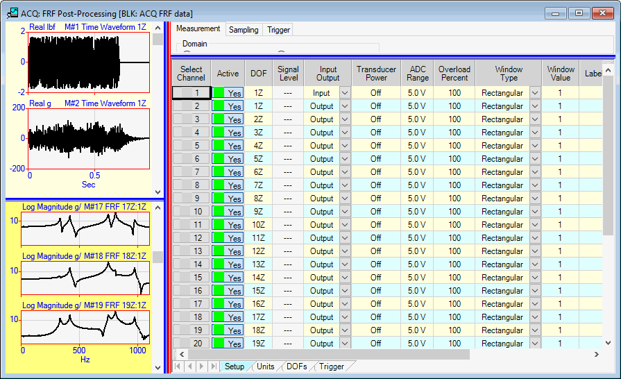
Several columns of data on this tab must be set up properly in order to acquire data from the connected front end.
If any property in this spreadsheet is not supported by the connected front end, the background color of its cell will change to purple.

Channels Spreadsheet Setup Tab.
Indicates the signal level for each channel during acquisition.
Used to enter a text description of each channel.
Defines the signal on a channel as either an Input, Output, or Both.
An Output is the numerator of an FRF, or the (moving) Roving sensor of a set of measurements.
An Input is the denominator of an FRF, or the (fixed) Reference sensor of a Cross channel measurement.
Applies either AC or DC coupling to each acquisition channel.
AC coupling removes the lower frequencies from a signal by applying a high pass analog filter to the signal before digitizing it.
AC coupling should be applied to all dynamic signals like vibration or acoustics signals.
DC coupling does not remove the lower frequencies from a signal.
DC coupling should be applied to all static or quasi-static signals like temperature, pressure, voltage or current.
Turns the power ON/OFF to the sensor connected to each channel.
Many types of sensors have built-in electronics and therefore must be supplied with power in order to operate.
Defines the input voltage range analog to digital converter (ADC) for each channel.
Defines the data type for each acquisition channel. Data type can be Translational (vibration), Scalar (temperature, pressure), or Machine Rotation (torsional vibration).
Defines the type of time domain window to be applied to a channel signal before any frequency domain signal processing is applied to it. Refer to the Signal Processing Commands chapter for more details on the use of these windows.
Used to specify a numerical value ONLY FOR the end of the Exponential window
The Exponential window uses the value in this column for the end of the window. The Exponential window starts at "1" at the beginning of the window
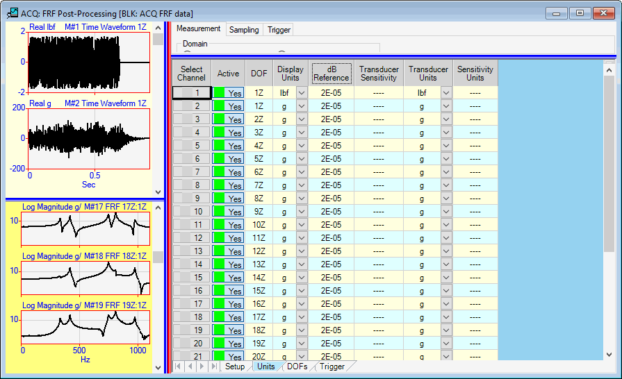
This tab is used to define the engineering units for each acquisition channel. M#s of acquired data can be displayed in the graphics area either in engineering units or in volts.

Channels Spreadsheet Units Tab.
Defines the acquired data for each channel in engineering units.
Typical Output units are displacement, velocity, or acceleration units.
Typical Input units are excitation force units (for an FRF calculation) .
Displays the upper graphics area (time domain) waveforms in either engineering units or volts.
If Units is chosen, each waveform in the upper graphics area is displayed in the units specified in the Units column.
If Volts is chosen, each waveform in the upper graphics area is displayed as the voltage of the signal acquired on its channel.
These three columns are used together to scale the data on each channel into the engineering units of the Transducer (sensor) using its Sensitivity Units. Sensitivity units can be one of the following,
Unit/V (engineering units per volt)
V/Unit (volts per engineering unit)
Unit/mV (engineering units per millivolt)
mV/Unit (millivolts per engineering unit)
If the channel Units (entered into the Units column) are different from the Transducer Units, the channel data will be integrated or differentiated from the Transducer Units to the channel Units, if possible.
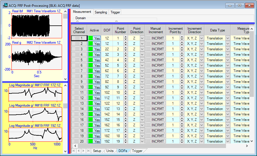
The properties on this tab are used to define & increment the DOF of each acquisition channel as each Measurement Set of data is acquired.
Using channel DOFs is optional, but it is strongly recommended as a convenient way of identifying where measurements were made on a test article.

Channels Spreadsheet DOFs Tab.
These two columns are used to select the Point number & direction of measurement for each acquisition channel.
Measurement Point numbers can be incremented or decremented by using the arrows in each cell, or they can be typed into each cell.
Measurement Point directions are chosen from the drop down list next to each cell.
Increments the Point number & direction (in their respective columns), according to the Increment Point By and Increment Direction By columns.
These two columns are used to specify how the Point number & direction are to be incremented when the Manual Increment button is pressed for each channel.