This menu is also displayed when you right-click in the graphics area in an Acquisition window
Opens a dialog box with a list of authorized Front Ends that can be connected to the Acquisition window.
Choose a Front End from the list and click on Connect to connect the Acquisition window to that Front End
Choose NONE from the list to disconnect the Acquisition window from a Front End.
Initiates continuous acquisition from the connected acquisition Front End.
Front End Scope acquisition will continue until Acquire | Stop (F6) is executed.
The time domain Number of Samples and the frequency Span per block of data are chosen on the Sampling tab
Time domain waveforms acquired from the Front End are displayed on the upper graphics area
Calculated functions are displayed on the lower graphics area
Calculated functions are chosen on the Measurement tab
Initiates data acquisition from the connected acquisition Front End.
Acquisition continues until the number of blocks of data required to calculate the number of Averages on the Measurement tab is completed, or until Acquire | Stop (F6) is executed
The time domain Number of Samples and the frequency Span per block of data are chosen on the Sampling tab
The status of the acquisition process is reported in the message box on the Toolbar
The acquired time domain waveforms are displayed on the upper graphics area
Calculated functions are displayed in the lower graphics area
Calculated functions are chosen on the Measurement tab
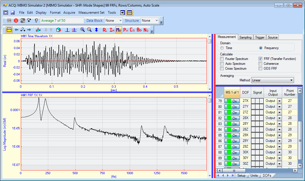
Acquisition Window During Data Acquisition.
Terminates data acquisition from the connected acquisition Front End.
During an Impact test (if a trigger has been enabled on the Trigger tab), executing this command will reject the last acquired block of data.
When checked, vertical & horizontal trigger lines are displayed on all active trigger channels of data in the upper graphics area.
When checked, two double hit lines are displayed on all active trigger channels of data in the upper graphics area.
When checked, overload lines are displayed on all active channels of data in the upper graphics area.
Channel overload is entered into the Overload Percent column on the Setup tab of the Channels spreadsheet.
Overlaod is entered as a percentage of the full scale voltage value of each channel.